for the primary datum feature, the surface errors will. Thank for your advices in advance.ĭmitrii Grishchuk. 1 Simulated datum A 2 Simulated datum B Each of the scale lines shall be contained within a tolerance zone defined by two parallel straight lines 0,1 apart which are symmetrically dkposed about the theoretically exact position of each scale line relative to each other. To simulate a deviated surface, generated random numbers are assigned to the appropriate direction (i.e. In SUMO I had only expirience of particular intersections simulating. What are possible solutions for this problem? As minimal, I need to simulate flows from-to random border nodes with defined in-out intensities.
SIMULATED DATUM DRIVERS
My purpose is to make cars drive to (from) objects O1-3 from (to) random border nodes, the other drivers should just move between random nodes, but known flows must stay unchanged. Předmět: Re: Simulating flows in network with defined border I am somewhat able to write simple scripts in R language, but I need to know how exactly the output (edge/turn data) has to look, or maybe there is another way to get it? 15, 2014 0 likes 8,964 views Download Now Download to read offline Engineering This presentation is intended for professionals who are in precision engineering works.
SIMULATED DATUM HOW TO
Both methods can follow the same design intent and are equally legitimate.Re: Simulating flows in network with defined border nodes intensitiesĪfter a close look on the related documentation I still cannot figure out, how to generate edge and turn counts basically from a scratch, with paper ribbon diagrams that I was supplied.
SIMULATED DATUM CODE
In the Machining Sequence dialog select an appropriate code generator.

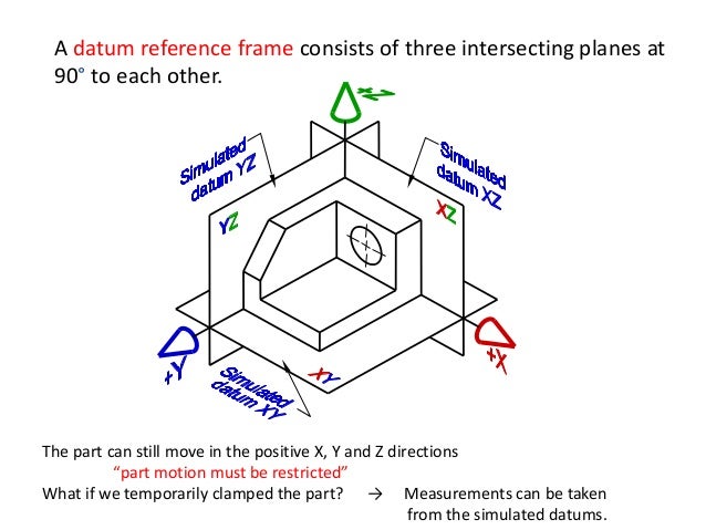
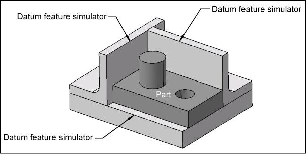
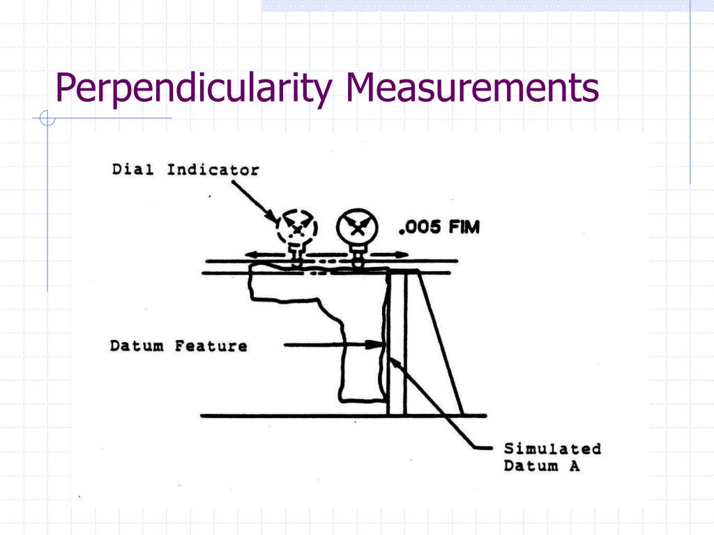
Datums have to be simulated in accordance with the product definition standard referenced in the drawing and should have exact geometrical relationship between them according to the basic geometry of the part, but the decision whether to establish them from a calculation based on sampled points or use physical datum feature simulators should be the inspection department's decision. Here are the key stages in using Machine Tool Simulation: Create part geometry as normal. Since there is form variation of the surfaces on the mating part, there is a very high chance that the 3/2/1 points involved with datum simulation are not the points that will contact the mating part at assembly. (Basically, we are allowed to flex the part with X pounds force, thus slightly moving the datum structure. These points are the only connection between the datum feature and the simulated datum. Simulated datum shift 08-08-2019, 05:12 PM The EIC of the newest project here wants to include 'A possible simulated datum shift' within an inspection program.


For secondary and tertiary you get 2 and 1 respectively. I'm not saying that any inspection method is superior or inferior to the other, but it is worth to keep in mind that depending on how much form error there is on a nominally planar surface, the "millions of points" mentioned above can be reduced to as little as three points of contact - and that is for a primary datum feature. If I need to use the granite as a datum plane (and I have on a few occasions) I put a pause in the program, instruct the operator to place a 1-2-3 block under where I have positioned the probe, continue the program, probe the block, another pause to instruct to remove the block, then rinse/repeat for however many points I need on the granite (I usually use 3 points).


 0 kommentar(er)
